Introduction
The way our summers are going, it has been difficult the last year without A/C. On the other hand it is a little strange to me that you have a significant issue when there is no working A/C on even a cheap car, but here we have a Yacht with a new price of almost half a million Euro, and there is no A/C on it.
Furthermore, all the pieces are in place. The boat has a Lithium installation, and a strong inverter, so I can run the A/C even without a generator.
I asked the dealer, who asked the Yard, and apparently not a single Skilso 35 has been delivered with A/C from the factory, and there was no current factory solution, so I had to make my own.
Initial planning
The objectives to meet were the following:
- A/C in both cabins and pilothouse.
- Enough power to cool the pilothouse even when the dividers are open when the weather is not super hot.
- Avoid losing too much storage room, as storage is always in short supply.
There was basically two options. Either fit a split unit (compressor in engine room, evaporator in pilothouse) or a self-contained one. The company I work with on the boat is a Dometic dealer, and good dealer support is a must. Hence it had to be a Dometic unit.
I wanted a unit with a variable speed compressor because it is much easier to size. With an on-off unit in our Nordic conditions the sizing is extremely tricky. We can have warm water of 23C and 30C outside, or we can have 18C water and 23C outside (but you want to run the A/C in the pilothouse if you don’t want to open everything). A fixed unit would experience a lot of short cycling.
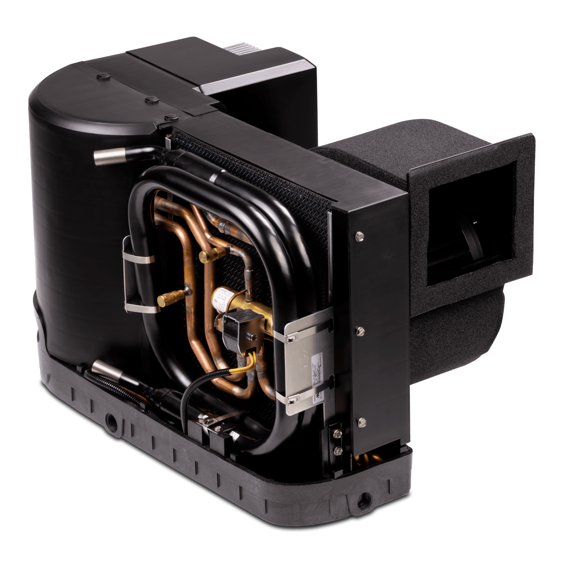
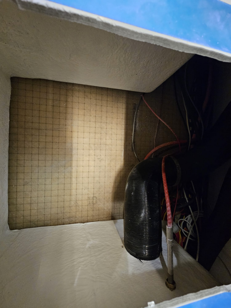
Dometic has the new GVTX variable self-contained unit, so it had to be that one, and split one was out of the question. Next was searching for the installation location. This absolutely had to be under the co-pilot seat. There is a large empty space there with nothing at all inside. Fitting it in the technical room is out of the question as the access to everything is significantly impaired, and putting it just under the seat would have completely consumed one storage room, which is also unacceptable.
Here is what the space looks like after you cut an access hole in the top under the seat:
The unit I decided on was the Dometic GVTX18:
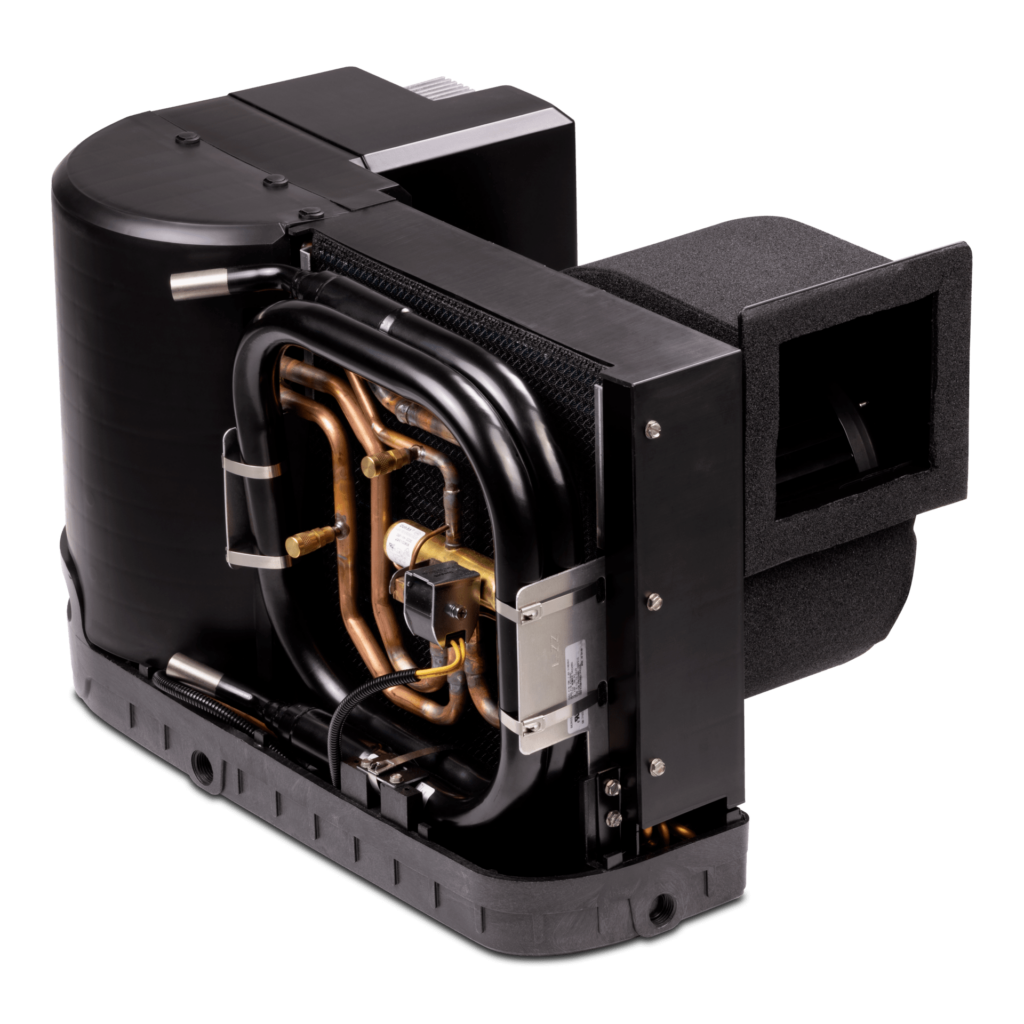
It is very powerful, but it can actually regulate down to around 4000 BTU, so even if you have conditions where you need just a bit of A/C, then you do not introduce short cycling.
The only thing that would be better than this is a multisplit unit with DX air handlers in each cabin or a chilled water system. However, this is very complex and eye wateringly expensive, we are talking adding 10-20% of the new price of the boat. Probably more important in warm climates, in our Nordic climate the water is usually cool enough that you never need A/C at night in the cabins, and since the boat already has electric heaters and the Ebersprächer diesel heater, it makes no sense to use the reverse cycle either.
Air ducting
The most challenging of all the tasks was the air ducting. For air conditioning you must solve the problem of the supply and the return air, and it has to be sufficiently dimensioned. There is no point to put a tiny duct somewhere nor one without an adequate return.
Cabins
The cabins have 90mm air ducting for the Ebersprächer heater, which splits into three. 90mm to the shower, 90mm to the center cabin and 70mm to the master carbin. Furthermore, there is an always open output in the corner by the co-pilot seat. This ducting can not be used for the A/C, but it can be used as our “return air” duct.
The first objective was to see if it is even possible to route another 90mm duct down behind the shower and split it the same way as the heater ducting – 90mm to the center and 70mm to the center cabin.
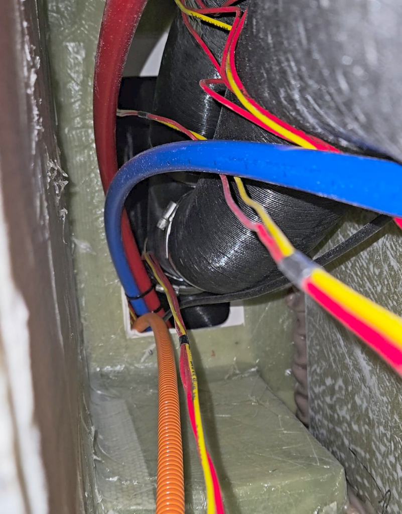
We used the Ebersprächer original tubing and it was possible to squeeze in another 90mm duct in between the existing heater tubing in the cutout under the port side of the dash. There is then access under the sink to attach the Y piece and pull the excess hose back up. It was super tight though and the original Y piece is in the way, but can be moved a little bit, here is what it looks like from below – filmed by sticking a phone in the hole beneath the sink, you can never actually see it with your own eyes:
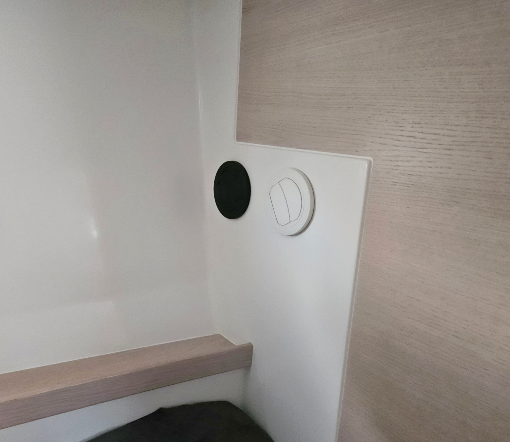
The center cabin was straightforward, there is a lot of room to cut another hole. Again, I used original Ebersprächer parts, but different color. The white outlet is for the A/C supply and the black outlet is for the A/C return and for the heater. Using the Ebersprächer output you can angle the cold air towards the ceiling:
The front cabin was a lot more difficult. It is impossible to run another 70mm line next to the heater one, there is just not enough room – or in fact anywhere else behind the panels. So we had to slightly abuse the cupboards. In under the sink, then up behind it, through the cupboard over the toilet, through to the other side and down to the outlet:
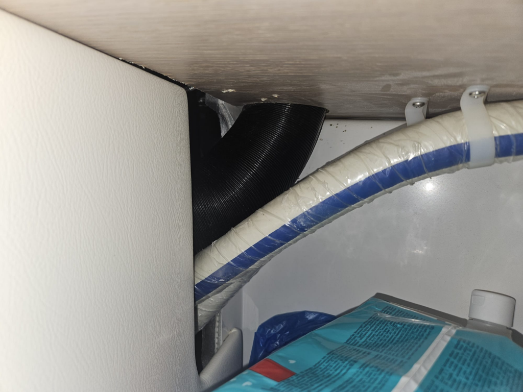
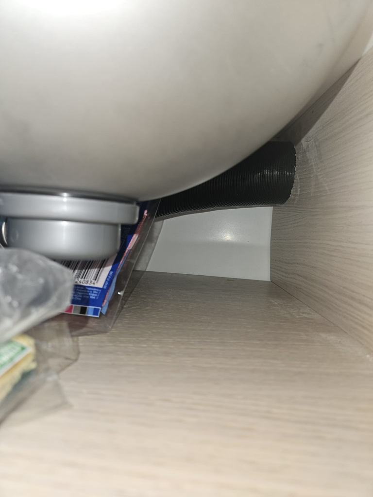
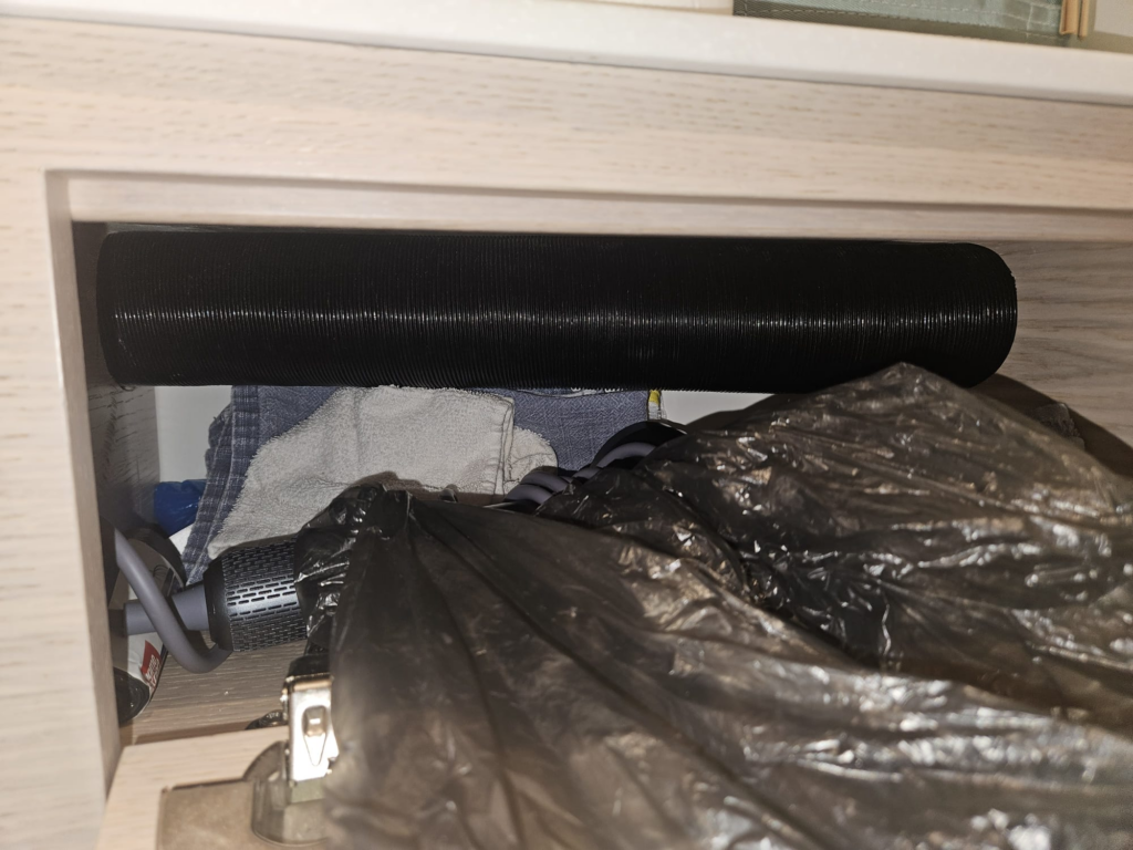
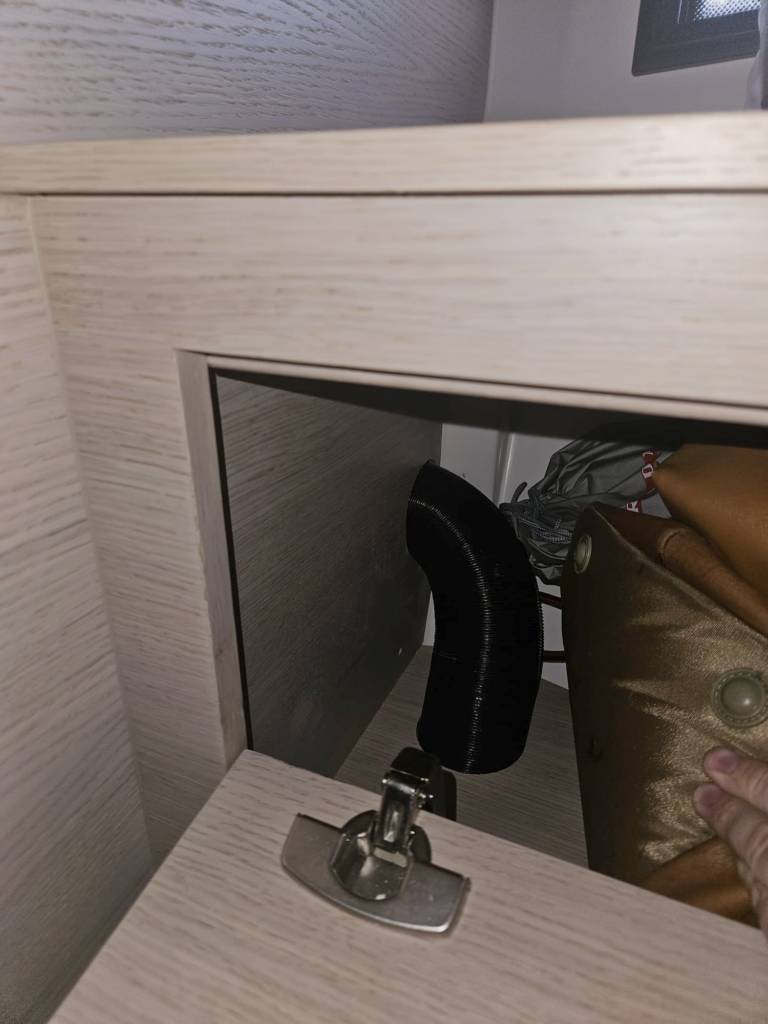
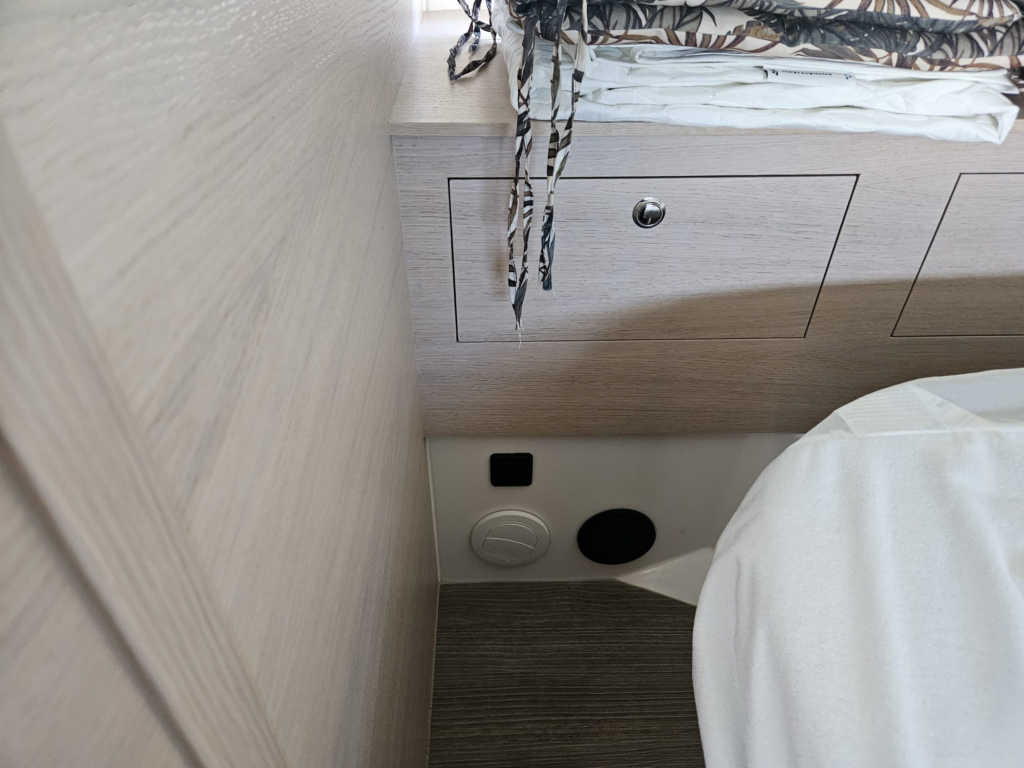
Realistically the only place where some useful room was lost, was in the corner of the storage locker in the Master cabin. Everywhere else the duct runs in places, which are in such a position that you can not put anything there anyway, unless you stuff the locker completely full. Fine by me.
Pilothouse
The ideal place for the main air duct is in the center column just above the technical room – it is possible to run a full 5″ (127mm) duct there. However, doing just that is not good enough. I wanted to have more air, also in part to satisfy the requirements provided by the Dometic datasheet to have sufficient airflow. The optimal duct size is 7″ according to the datasheet.
To accomplish the goal I decided to re-use the four defroster outlets:
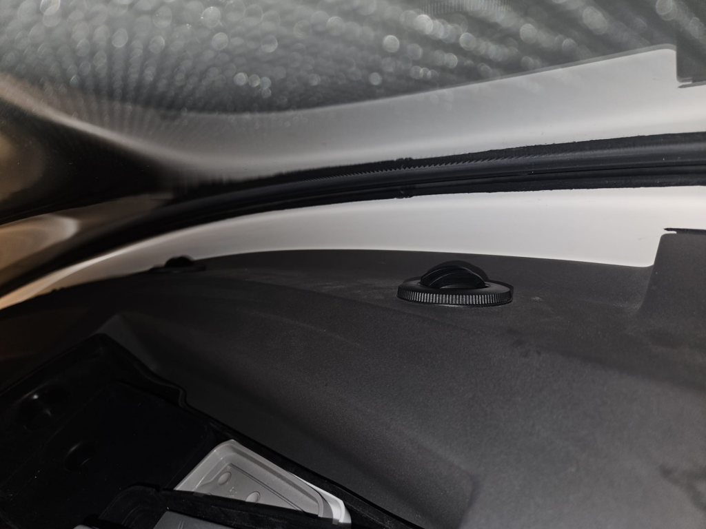
The issue is separating the A/C and the defroster air. This has been done before – by https://nbmarine.se/, however the design there was one with an electric actuating valve, and I do not like using electronics just for the sake of it when something can be solved in a simpler fashion.
The defroster nozzles have 3x60mm ducts running to them. The objective was to design a device that allows air to flow from the defroster and A/C to the nozzles, but not from the defroster to the A/C or from the A/C to the defroster. This can be achieved with two non return valves:
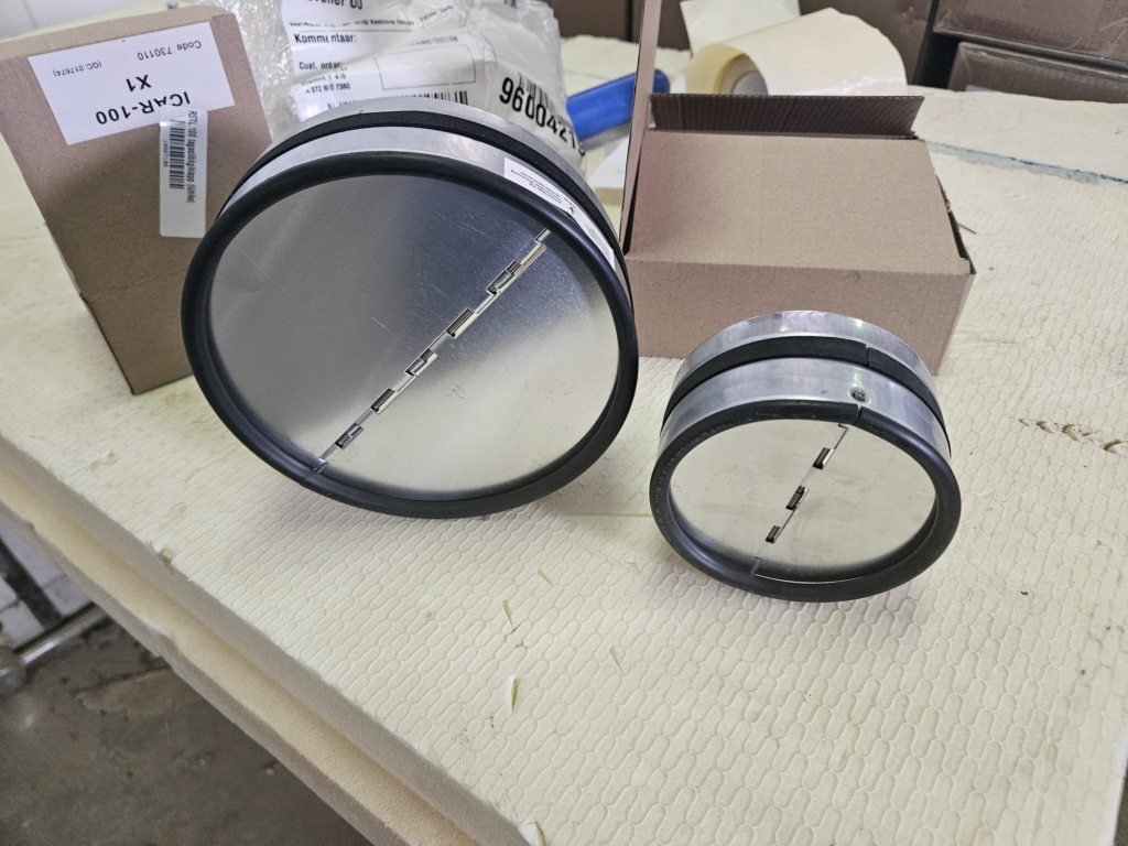
Here is the design I came up with:
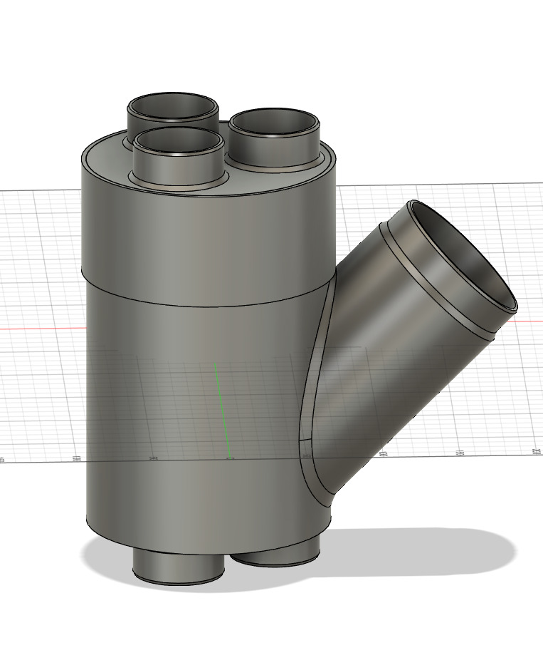
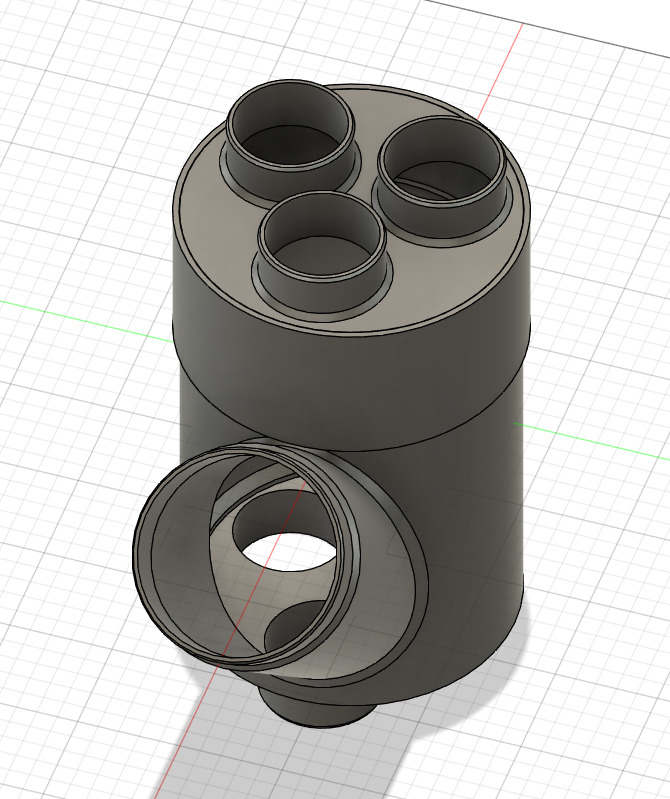
3D printed model with the valves in place:
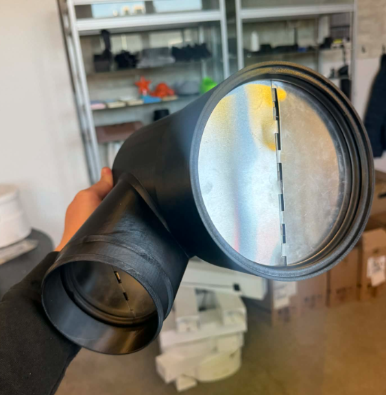
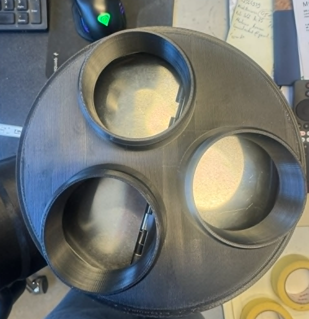
And here it is with everything glued together and acetone smoothed for the finished look (and to prevent air leaks between layers):
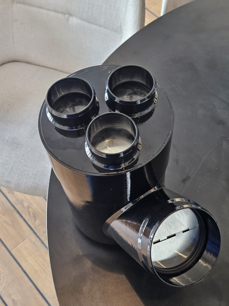
The A/C air enters from the side, the entry is 100mm. The cross sectional area is around 7800 mm2. The three defroster nozzles enter from the top, are around 8400mm2, and then everything exits from the other side. The valves prevent the air going anywhere except through the ducts below the windshield. Simple, no electronics needed. The valve butterflies are aluminum and the springs and shafts are stainless steel, they should last for a very long time.
Fitting the main duct was fairly anticlimactic in comparison. I got a 5″ backbox and a 4″x10″ supply grille from MSI Marine in the USA, and the rest was just some cutting and running a flexible duct.
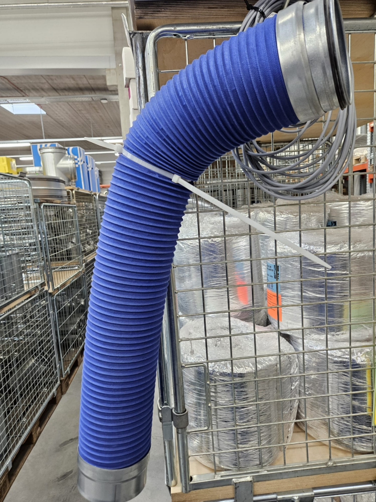
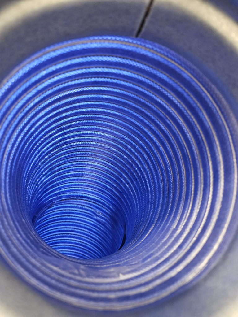
The flexible duct is Smoothdec 5″. The benefit of this duct is that it is flexible enough, but does not lose any diameter due to being still quite rigid. In comparison all kind of 5″ accordion ducts are more like 3.5″ when they are not fully extended, and it’s almost impossible to fully extend them on a boat. Here is what it looks like in the store:
Just had to run it to the technical room, and we slightly enlarged the opening where a duct was, to get it behind the center column:
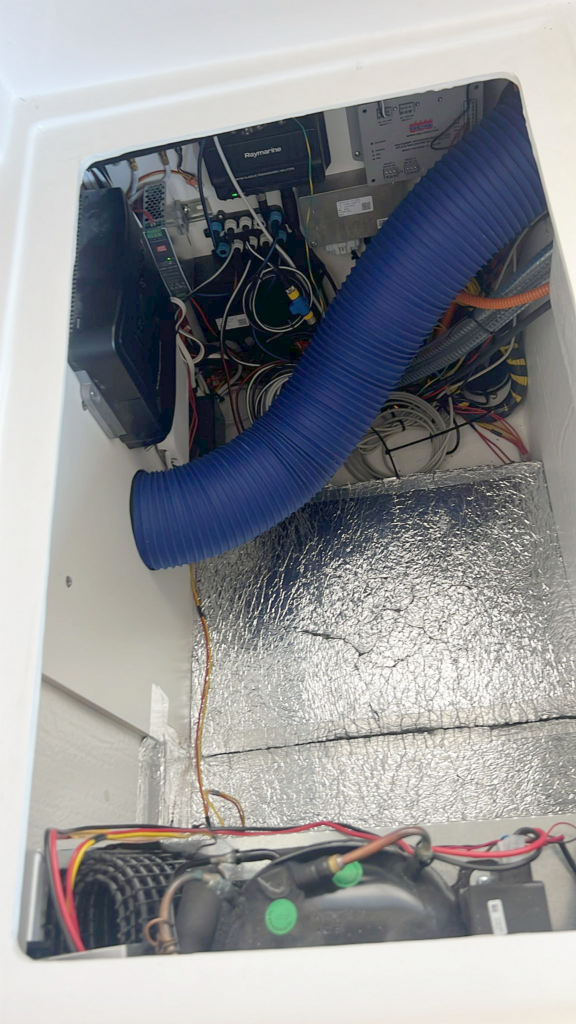
Then we cut away a small layer of the veneer, just deep enough that the backbox sits flush. That way it is not needed to screw it in and as the top panel holds it firmly in place. Then if you need to work on something, you can just bend it down out of the way.
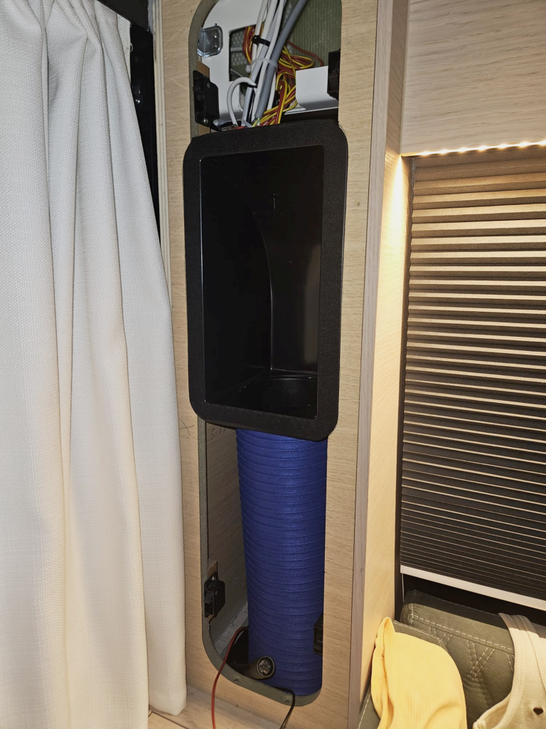
Here is the final result – I fitted a 4″ x 10″ supply grille, because it looks better (more central on the top cover) and the cross sectional area of the grille is about twice the size of the 5″ duct anyway, so there is no flow restriction:
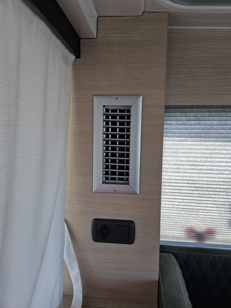
The air is directed upwards and does not blow on you even if you stand in the doorway or in the galley, instead it is diffused evenly in the pilothouse.
Blower connection – the elephant in the room
All the end-ducts were in place at this point, but how to connect them to the A/C?
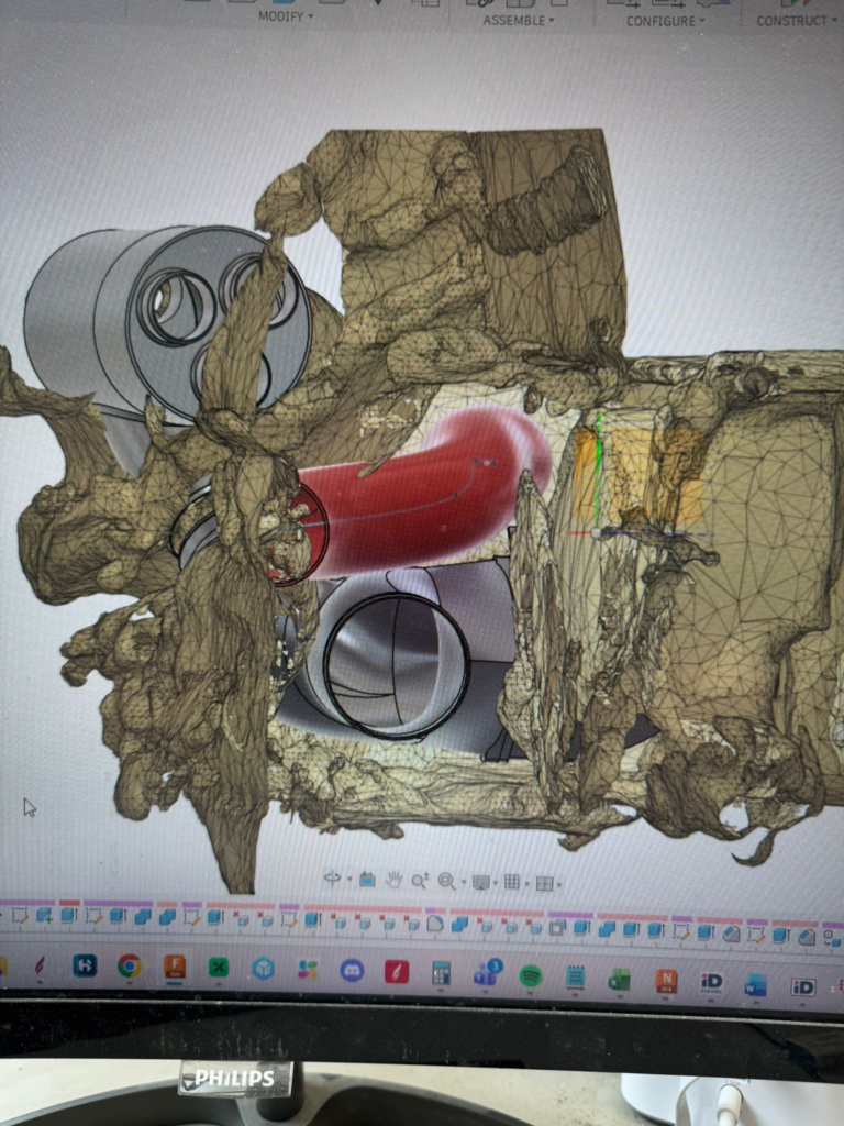
As the room is super tight, and everything is very precise, yet flow sensitive, the only way was full modeling. The first step was to 3D scan the interior and make some rough lines:
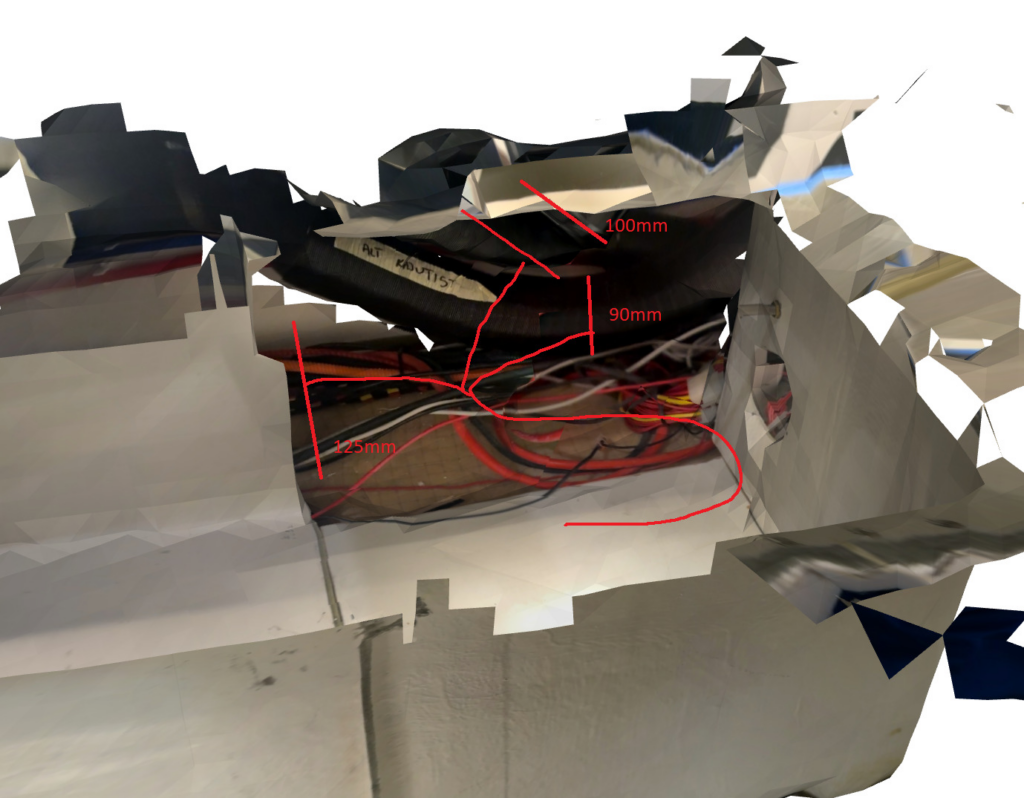
You can see the 90mm hose coming from the cabins and the 100mm entry sticking out from the defroster/AC air divider.
Here is the unit roughly in place:
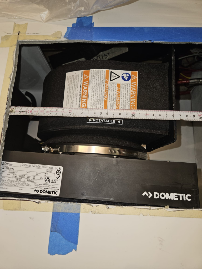
It is difficult to express in just pictures how much effort it took. Unlike the cylindrical air divider, this was above my pay grade as I do not do 3D modelling professionally. It took us 2 weeks with a professional 3D company to go from concept to printed model.
Here is the semi-finished model, modeled with the blower and the defroster divider:
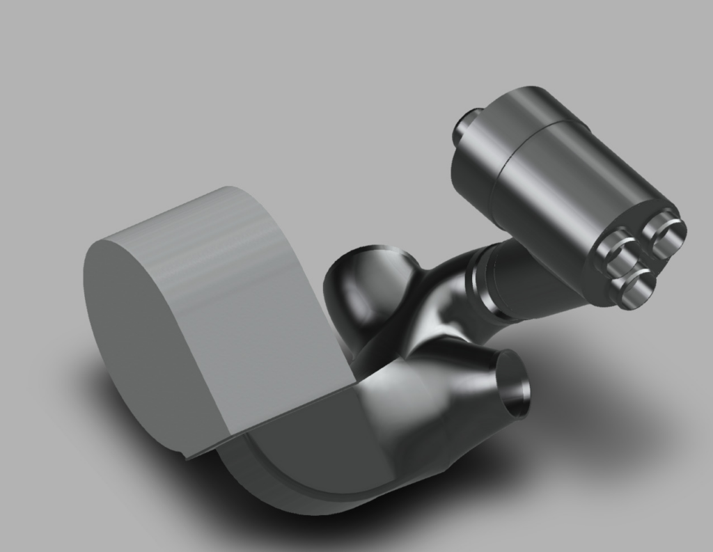
It was important to make sure that the flow is also good, so I ran CFD analysis and we made multiple iterations to improve the flow and remove chokes. I also made sure there is no significant pressure drop and I tested at 550 CFM, which should be roughly the capability of the blower. Here are some pictures from the flow testing software in the final iteration:
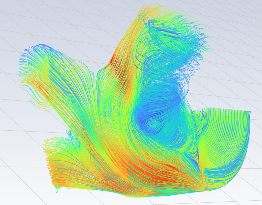
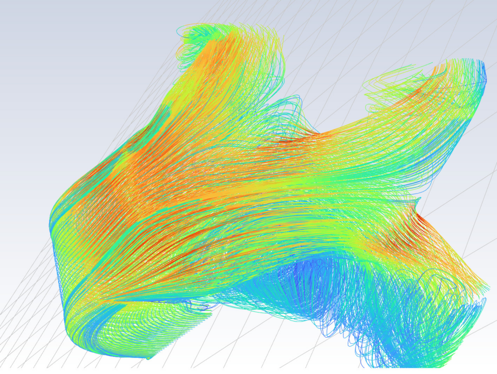
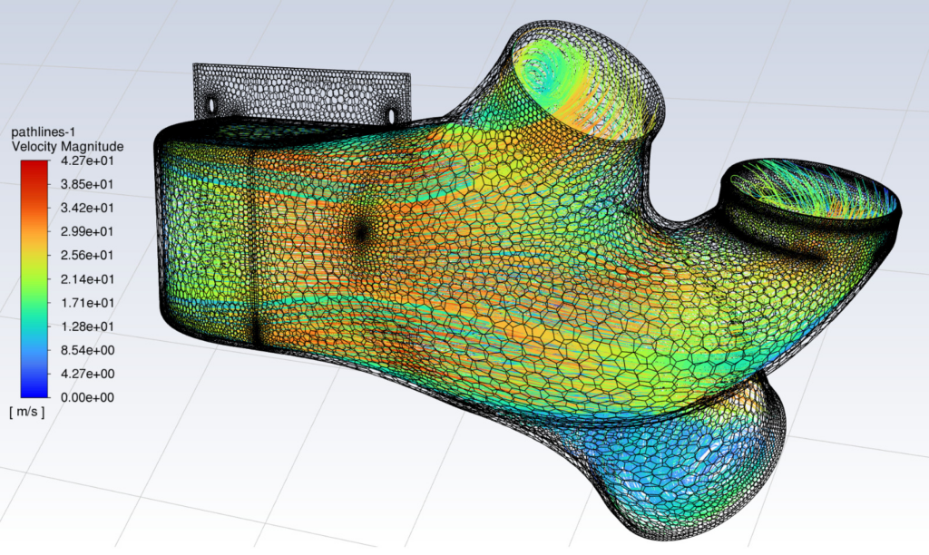
While not ideal, this is the best we could do given the limited space. We had to also re-locate the Ebersprächer output and the Surefire line. Everything was modelled in the 3D scans (red is new heater output):
The part was again 3D printed in 2 pieces from ABS plastic, glued together and smoothed with acetone vapor. Here is the first test fit of the part:
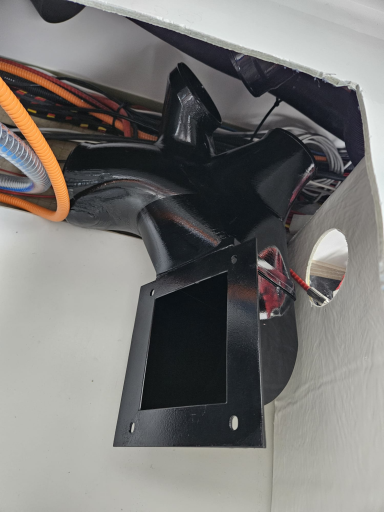
A more exact test fit using zipties:
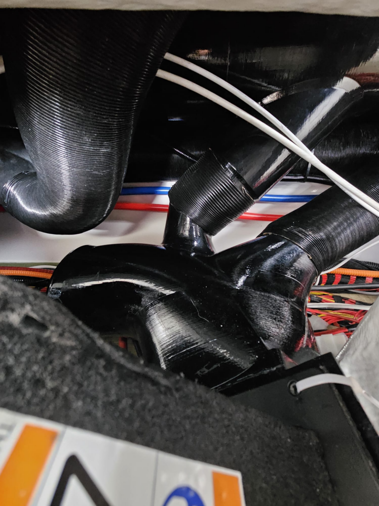
Almost in place, a bit to go to the right – we managed to do it by rotating the blower a little more, you can also see the return air grille for the first time, which is also made by MSI and is a 10″ x 14″ directly by the blower suction side.
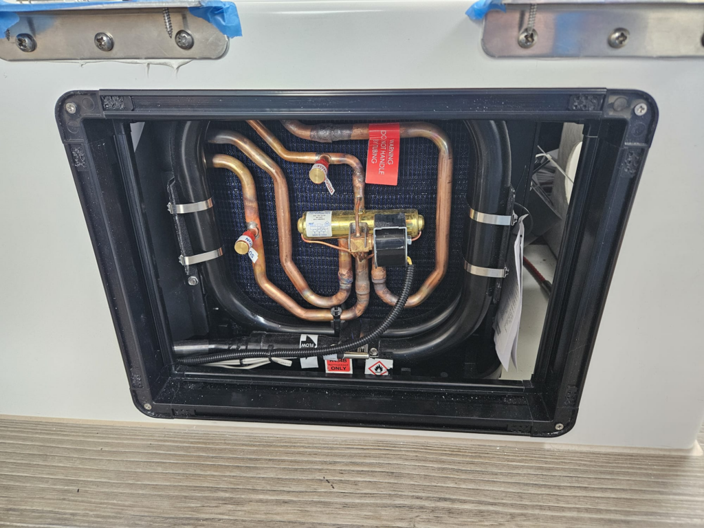
Additional return is provided by the old heater outlet, which is now just a vent, and the real heater outlet is on top of it:
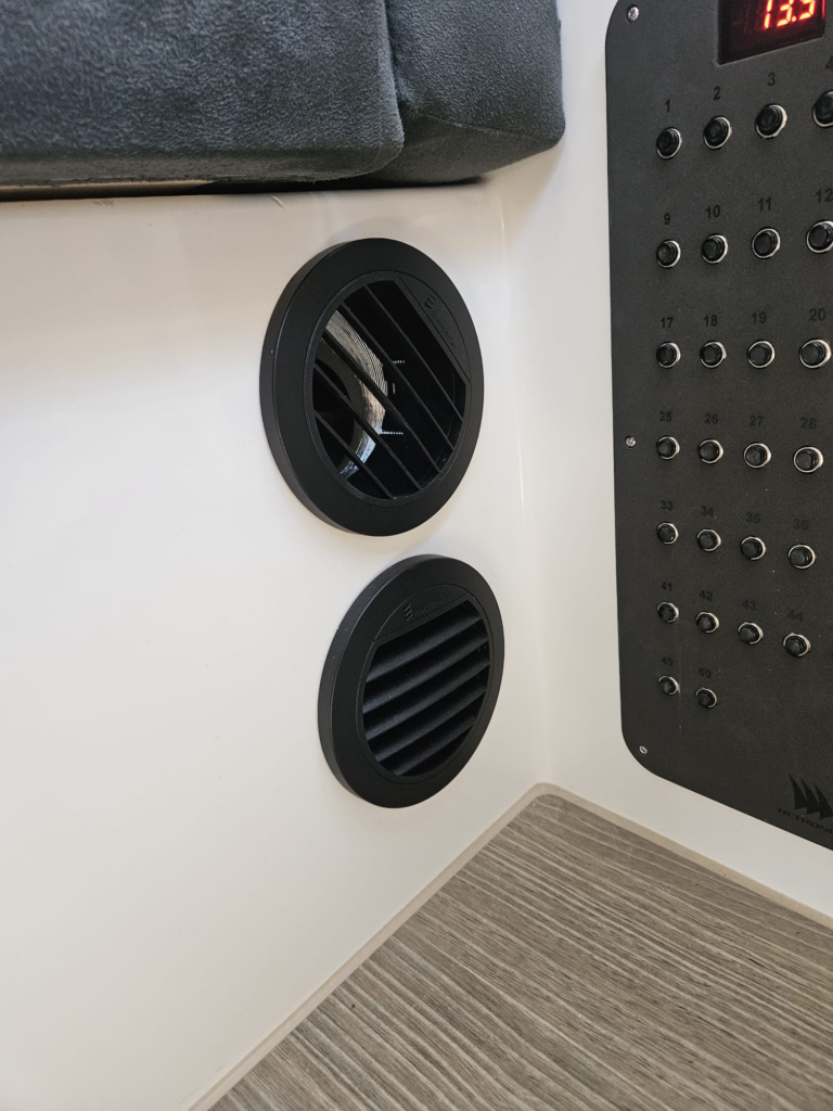
This works to easier draw in the return air from the cabins.
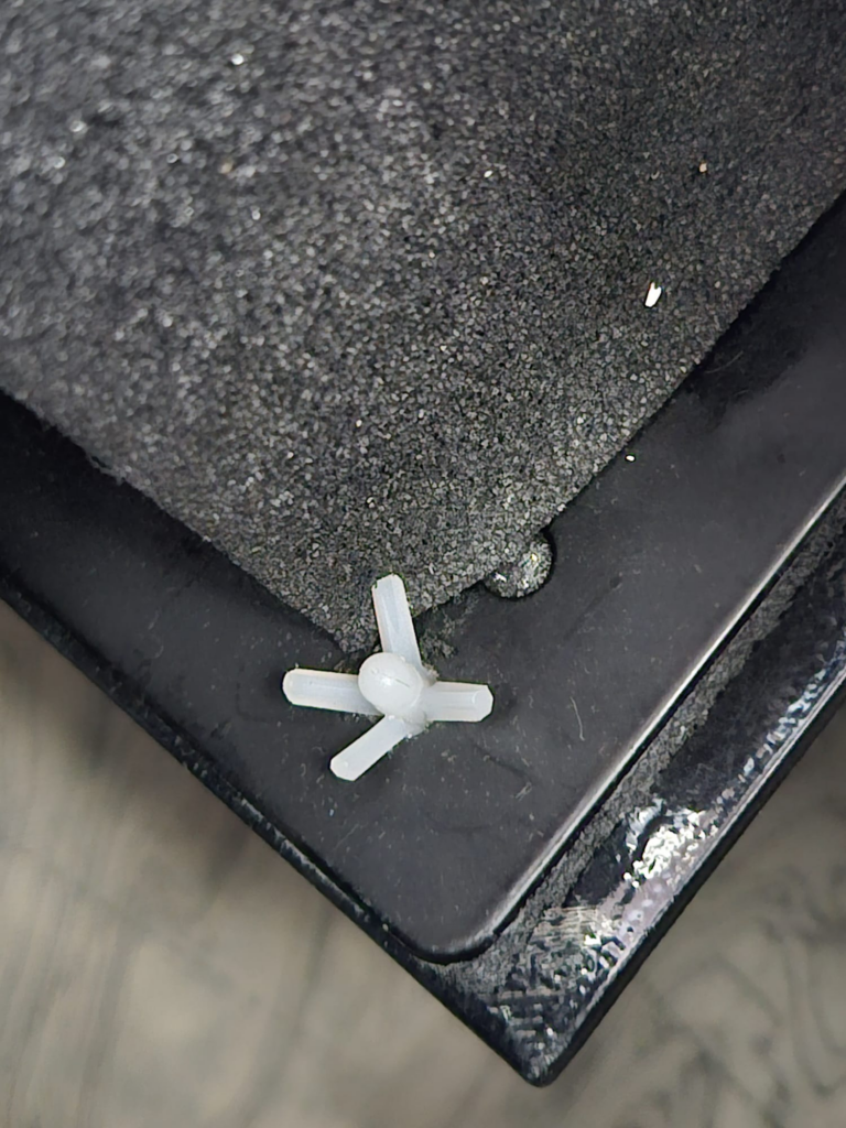
Finally it was time to rigidly attach the output adapter. We used plastic dowels and a ton of elbow grease:
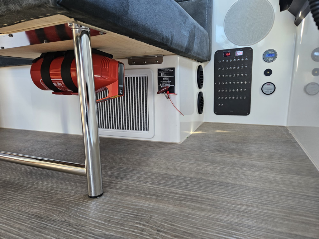
And this is how it looks all put together – the fire system had to be moved as well:
The “money shot” is the one from the storage area, as it shows that we lost perhaps 15-20cm of the storage bin, maintained access to the technical room and gained A/C:
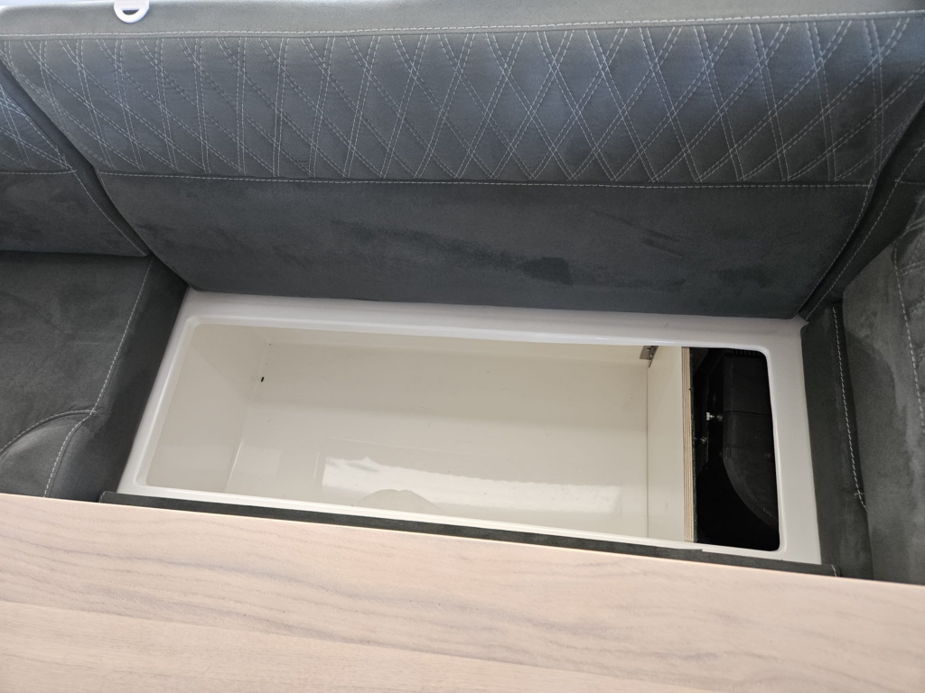
Airflow calculations
Dometic recommends a 7″ supply air duct for 18000 BTU, in general 5″ to 7″ ducts are acceptable (but at a lower rating). Here are the cross-sectional areas in millimeters:
Base case – 7″ duct: ~24800 mm2
Cabin supply open: ~26900mm2
Cabin supply closed: ~20500mm2
With the cabin supply open we comfortably exceed the recommended duct size for 18000 BTU. With the cabin supply closed, it is lower by about 18%, but since the unit is variable, it just adjusts itself.
The rest of the plumbing
Everything else is fairly routine. The unit needs a condensate drain and seawater supply & return as well as a 230V electrical connection. All the plumbing can be routed via the technical room into the engine compartment.
The condensate drain we just routed with a T piece into an existing water drain from the deck:
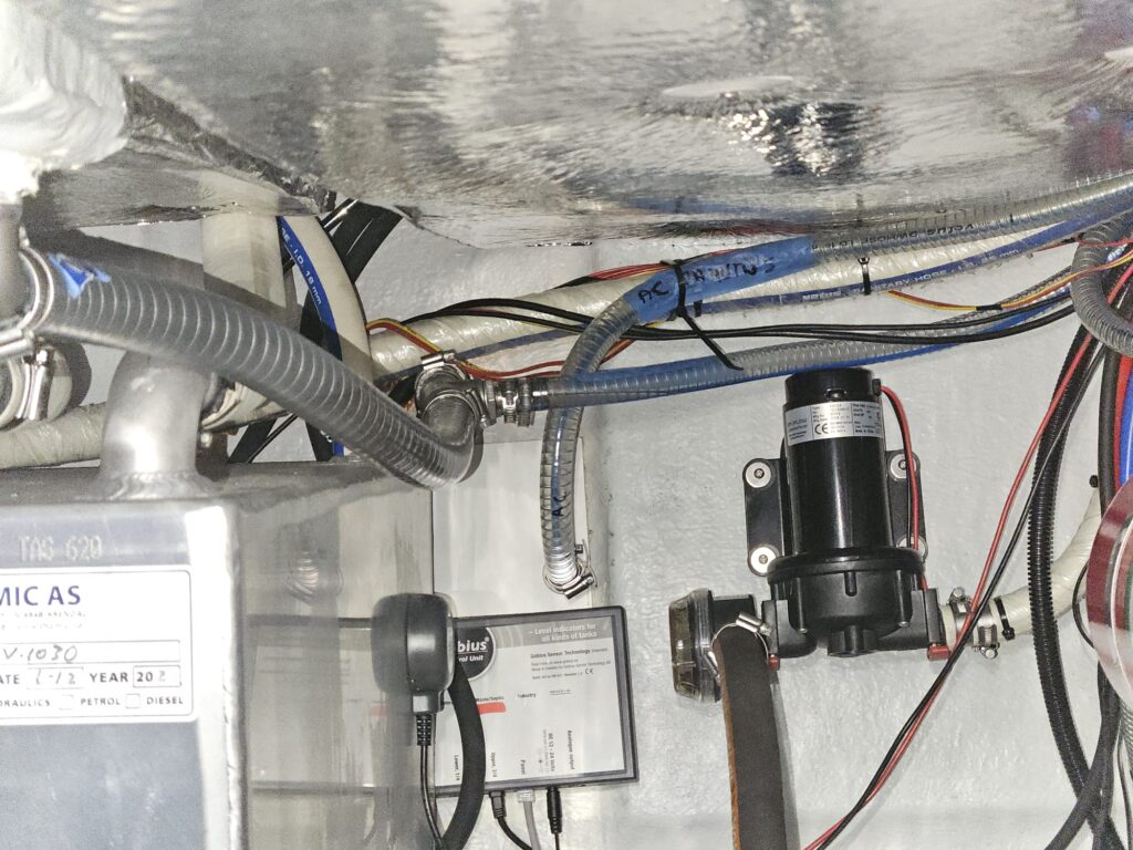
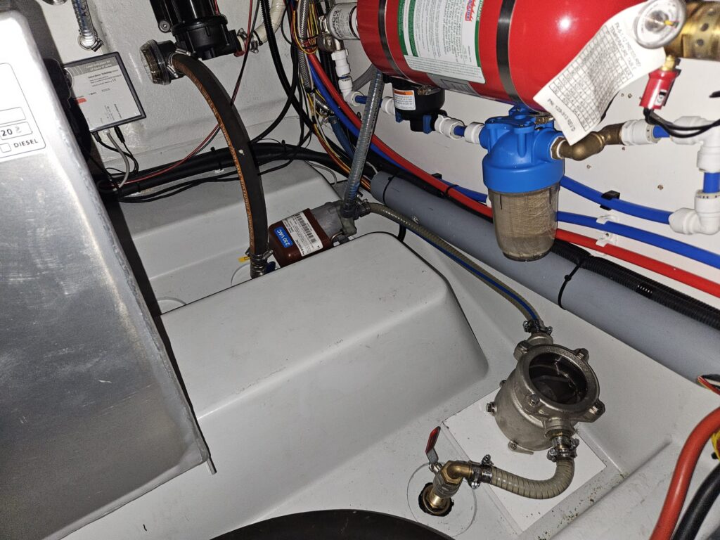
For the seawater pump a hull penetration had to be added on the side for the return and a kingston valve with a scoop fitted for the pickup. This is all done in the engine room, the only thing to pay attention to is to have the strainer and seawater pump below the water line, as the seawater pump is unable to prime itself otherwise if the system was drained for some reason or sucks some bubbles. With the scoop it primes itself as soon as the boat is moving.
The electrical connection was done as usual with a Defa T piece and extension cable, where one end was cut off and routed into a breaker which can be conveniently reached with the storage opened:
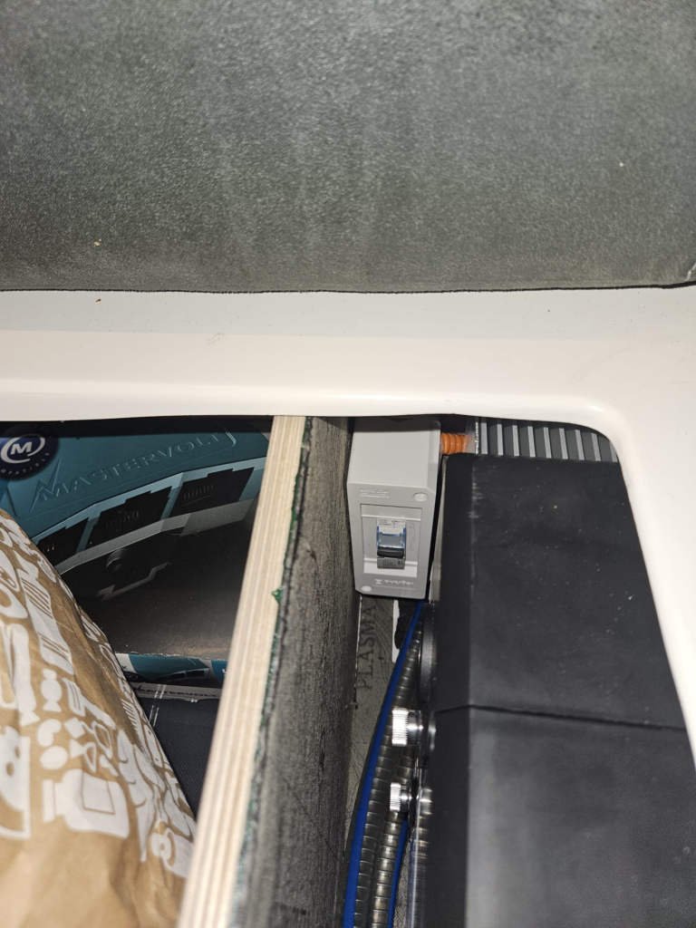
If you pay close attention you can also see that we lined the entire area with 4mm noise/vibration isolation mat to make the installation quieter. This makes a noticeable difference for the audible compressor noise.
Operation
We had some warranty issues commissioning the unit (the first one had a defective expansion valve), but this is all mostly ironed out now and it works really well, it just needs some tweaks to the parameters for our colder water – it’s just not usual to have 18C water and 28C outside in countries where the A/C was developed. I have to give a shoutout to Martin at Dometic Sweden for first class support here.
The power of the A/C is sufficient to keep the saloon at 24C even with 30C outside as long as you use the shades. Or you can cool the entire top part of the boat with the canopy closed when it’s not so hot outside. Also when it’s let’s say 23-24C outside but you’re on plane in the sea with a lot of spray, you can just turn the A/C on and not worry about the saloon getting wet or being hot.
Cooling the cabins works great as well, but of course you only have manual control over it, however the middle cabin never needs any cooling in our climate (gets cool enough by the seawater), for the front cabin it is usually enough to give it a blast for 30 minutes in the evening if it heat up during the day, and when the sun is not out the seawater again does the rest of the job.
On the 800Ah battery bank the A/C can easily run for over 8 hours in fairly demanding conditions. it draws between 400W and 1100W depending on the amount of BTU requested.
The only improvement in the pipeline is to install a second alternator (the Yanmar 6LY440 has a factory kit for that, which is already ordered), because currently if you are at displacement speed with ~1100 engine RPM then the A/C at a high operating point consumes all the excess power produced by the alternator, so it can be actually slightly (~100W) discharging the batteries. On plane the output of the alternator is significantly higher and there is no such issue anymore, of course it would still be beneficial to have a second alternator just for charging the lithium bank faster.
Conclusion
This is by far the biggest project I have ever done on a boat. All the custom pieces and the modelling, trying to squeeze things into impossible places…
But it is better to do something right or not do it at all, and it feels good to have this right. Certainly having A/C on the boat has been a game changer for comfort onboard.