Introduction
There are a few ways to increase autonomy, and fitting more energy storage is one of them. When starting to research the topic many different opinions were circulated on social media. From full systems to drop-in batteries to fitting non-marine rated battery bank style accessories and everything in-between. I like doing things right, so the non-marine solutions were not on my radar.
Mostly it boils down to either fitting drop-in batteries with built-in BMS in each battery or making a proper solution with a single BMS.
There are no advantages to using drop-in batteries besides ease of installation:
- Drop-in batteries are heavier and bulkier.
- The peak discharge current is significantly lower
- The charging profile is different for AGM and LifePo4, so it is not ideal to have them both charging together
The following points needed to be taken care of:
- Correct battery charging
- Battery overcharge protection
- Retaining emergency parallel logic
- Protecting the 6LY440 Denso alternator from overheating
The decision was made to fit a full Victron system.
Main system schematic
Victron has a very good example system schematic:
VE-Bus-BMS-example-with-3KW-12V-MultiPlus-230-Volt
This is the core of the system.
I used 4x Battery Smart 200Ah, for a total of 800Ah or roughly 10kWh, and everything else as in the schematic. if you would fit standalone batteries the maximum you could get in is about half that, as the batteries are much bulkier due to each of them having it’s own BMS.
If you want the installation be up to code, then you should use Class T fuses for the batteries. I used the Blue Sea ones.
I also used a separate Victron Smart 13A charger for the engine bank, because the charging and float voltages for the AGM and LiFePo4 batteries are different.
Emergency parallel
From factory there is no separation between engine and house bank when the engine is running. Everything is handled by a BEP marine VSS switch:

It connects the house bank and engine bank together whenever it sees more than 13.7V, and disconnects it around 12.5V.
If you send a momentary signal to it, it will also forcibly connect the two banks.
With the Argofet isolator this no longer can be used. You have two options: Remove the emergency parallel function entirely (I don’t like the idea) or fit a normal battery style switch.
However, now you get another dilemma. If you fit a normal switch that allows current to flow two ways, then when the parallel switch is on, you are essentially bypassing the BMS. This means if the emergency parallel is on (e.g. by accident) and then you have some problem with the alternator regulation, you could potentially start a fire. The likelihood is small, but it makes sense to design so it can never happen.
This is the solution I came up with:
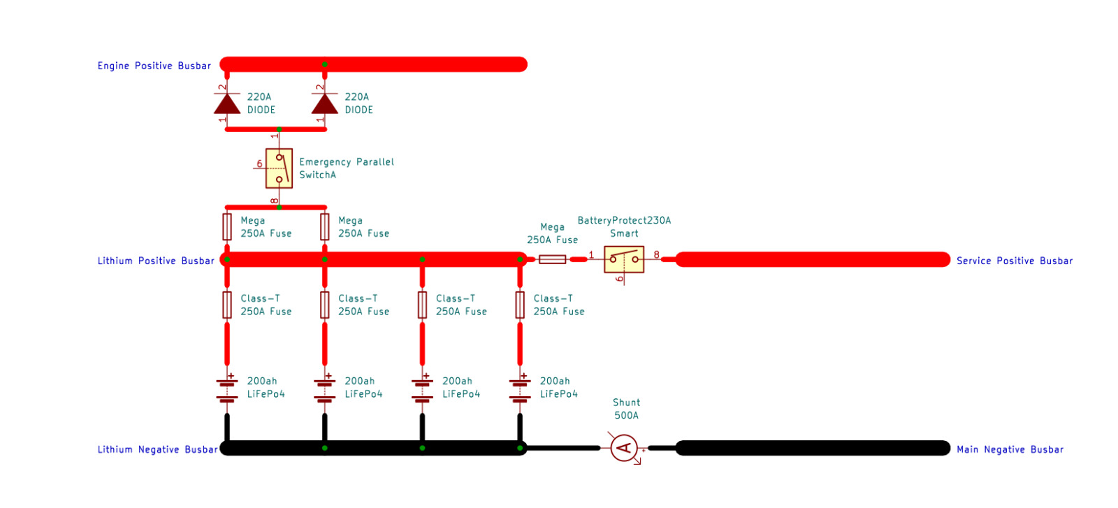
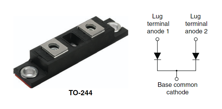
I found a dual 220A diode (440A total), which is plenty enough for the starter. Part number is VS-440CNQ030PBF. It has two anodes, the cathode is all copper and it bolts to a bus bar:
Then just replace the yellow VSS switch with a drop-in BEP motorized switch and change the button in the panel from a momentary pushbutton to an on/off button like the two others.
Installation
After you remove the batteries, you realize that from the yard there’s quite the rats nest behind them:
The first step is to tidy up all that mess – Viknes why not like this from factory?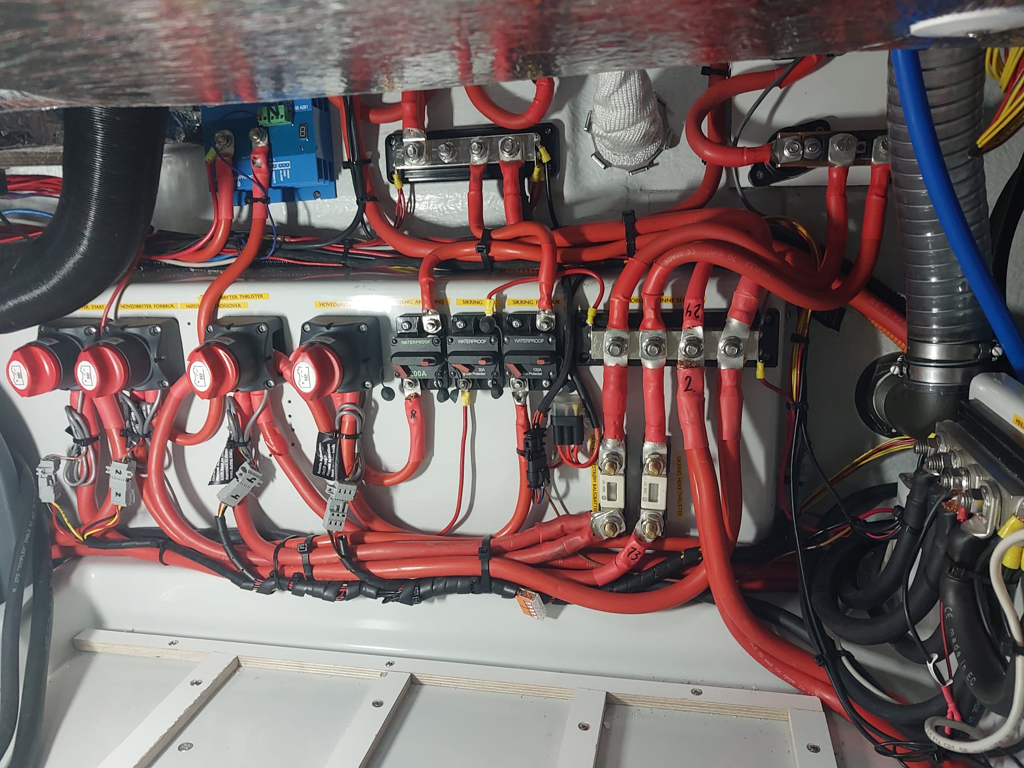
You very quickly run out of space to fit the new components, so extra veneer needs to be bonded to the hull, we chose the area above the boiler and also relocated the DEFA TV inverter there: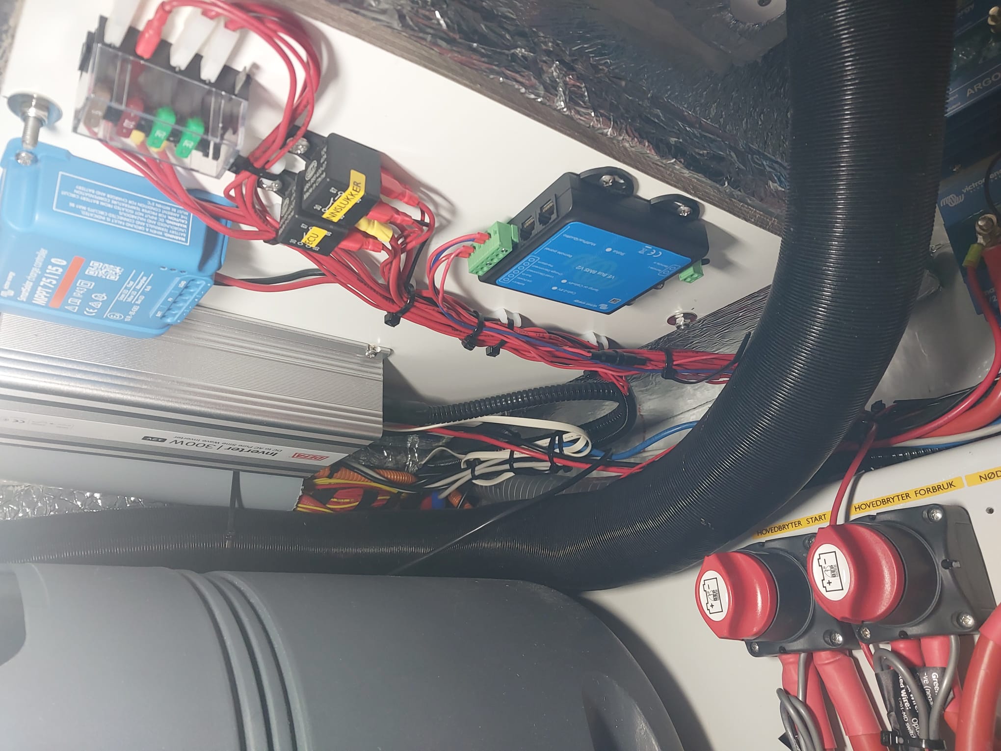
The Lithium busbar went to the right partition: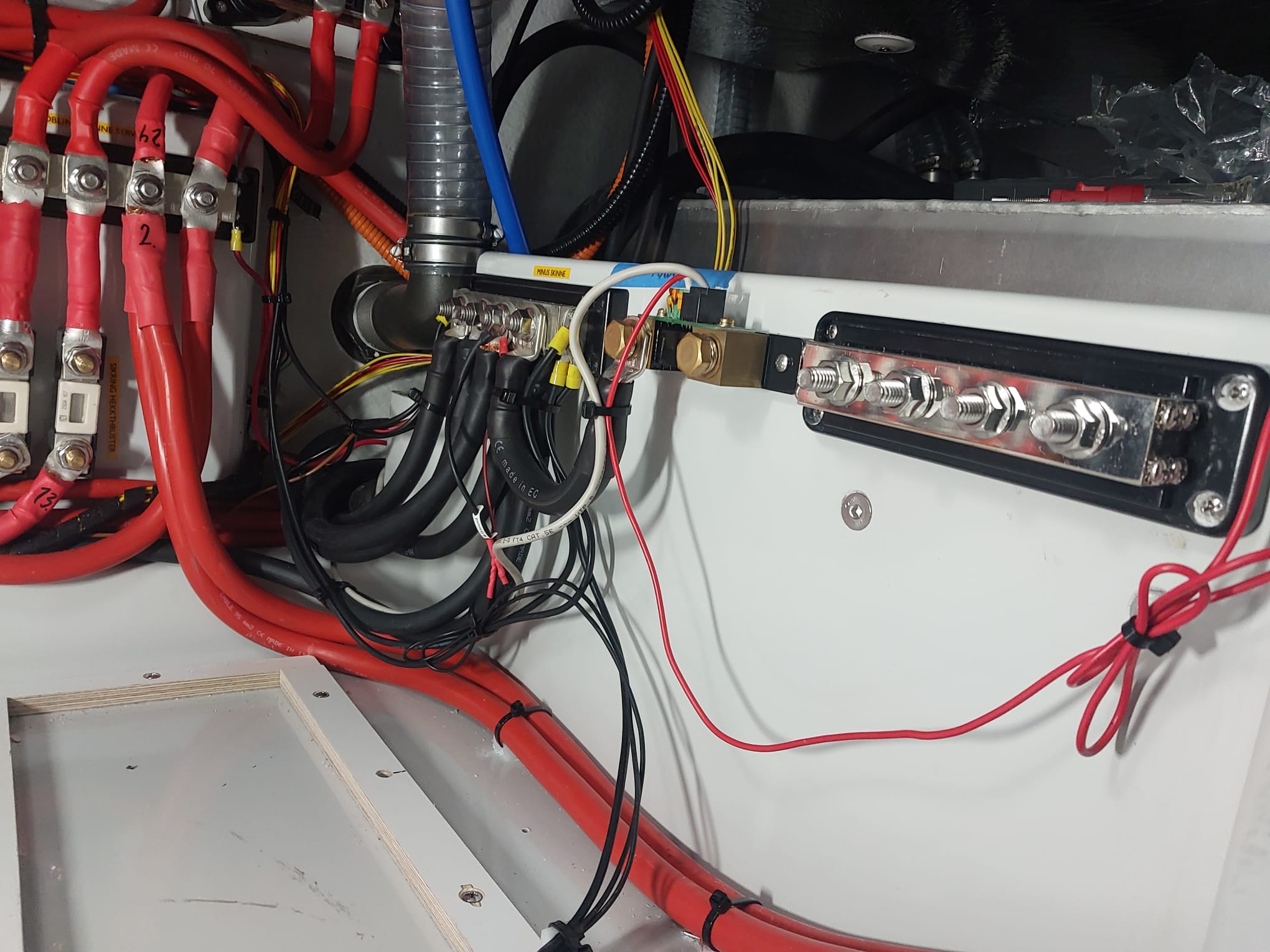
Furthermore, the decision was taken to move all the lithium batteries to the back and have the starter AGM batteries in the front, because those need to be replaced eventually, and it would suck to take everything out every time. Here is the first test fit of the batteries: 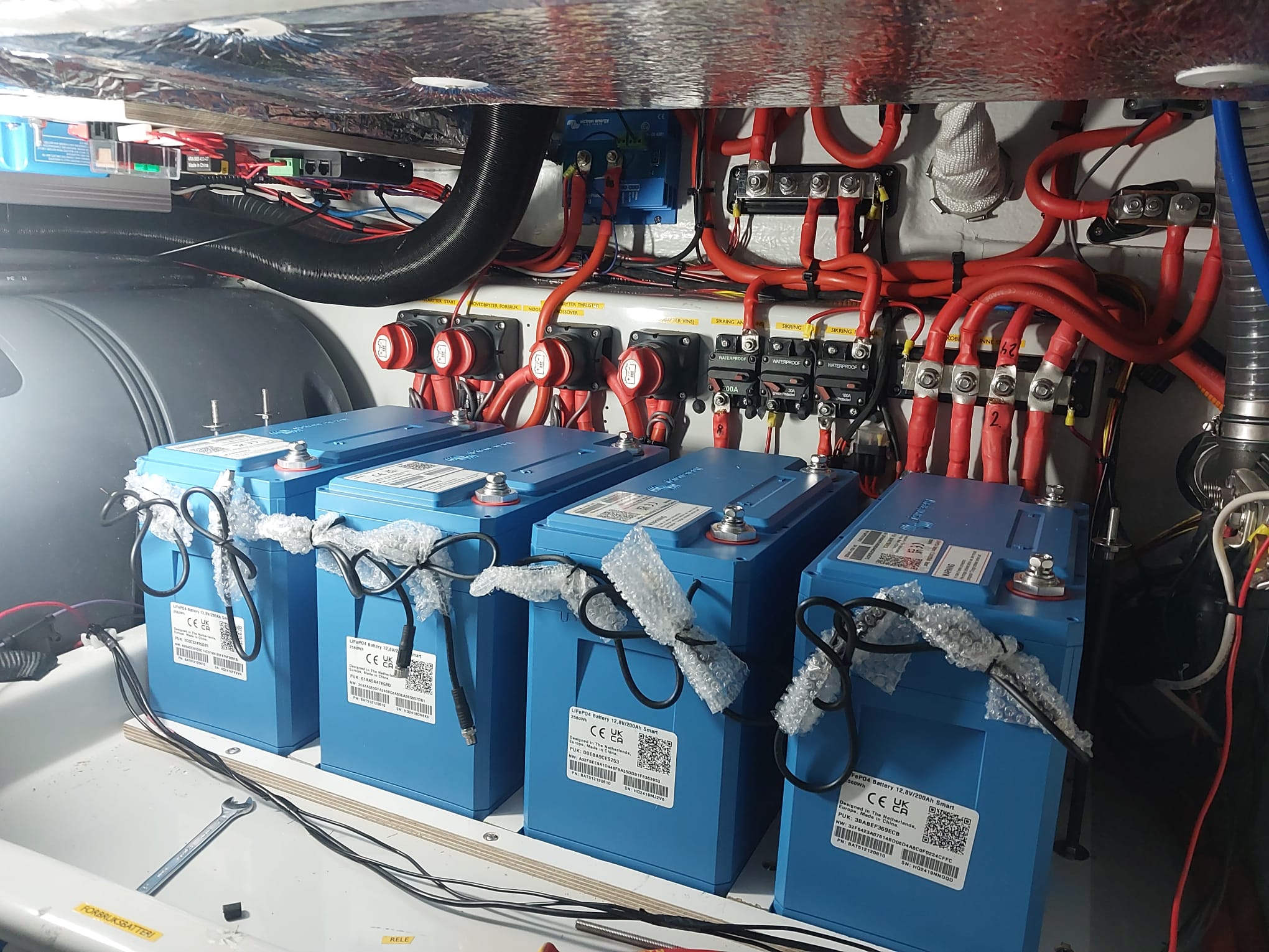
The Class T fuses are quite big: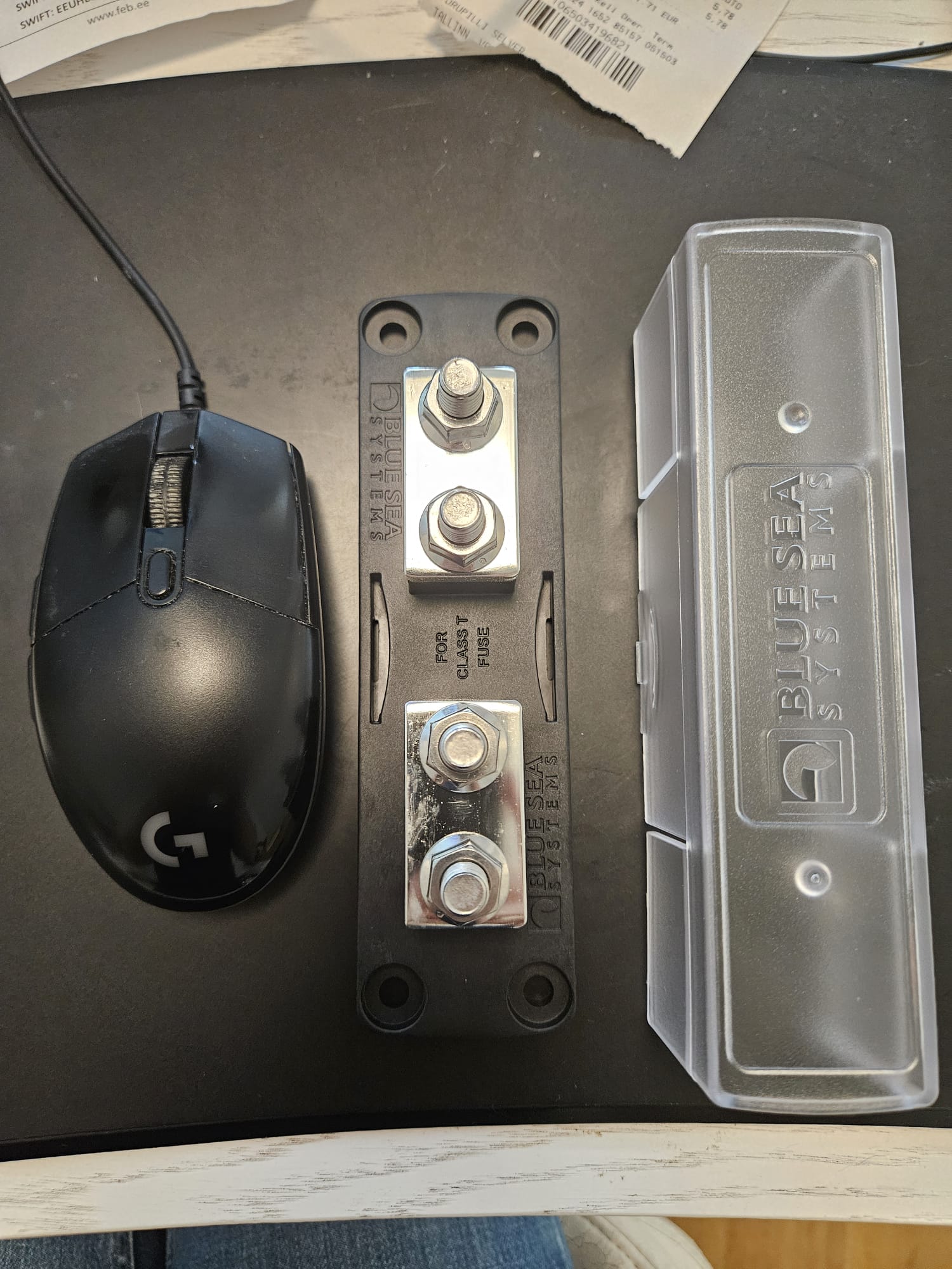
We decided to mount them above the batteries, together with an emergency OFF switch: 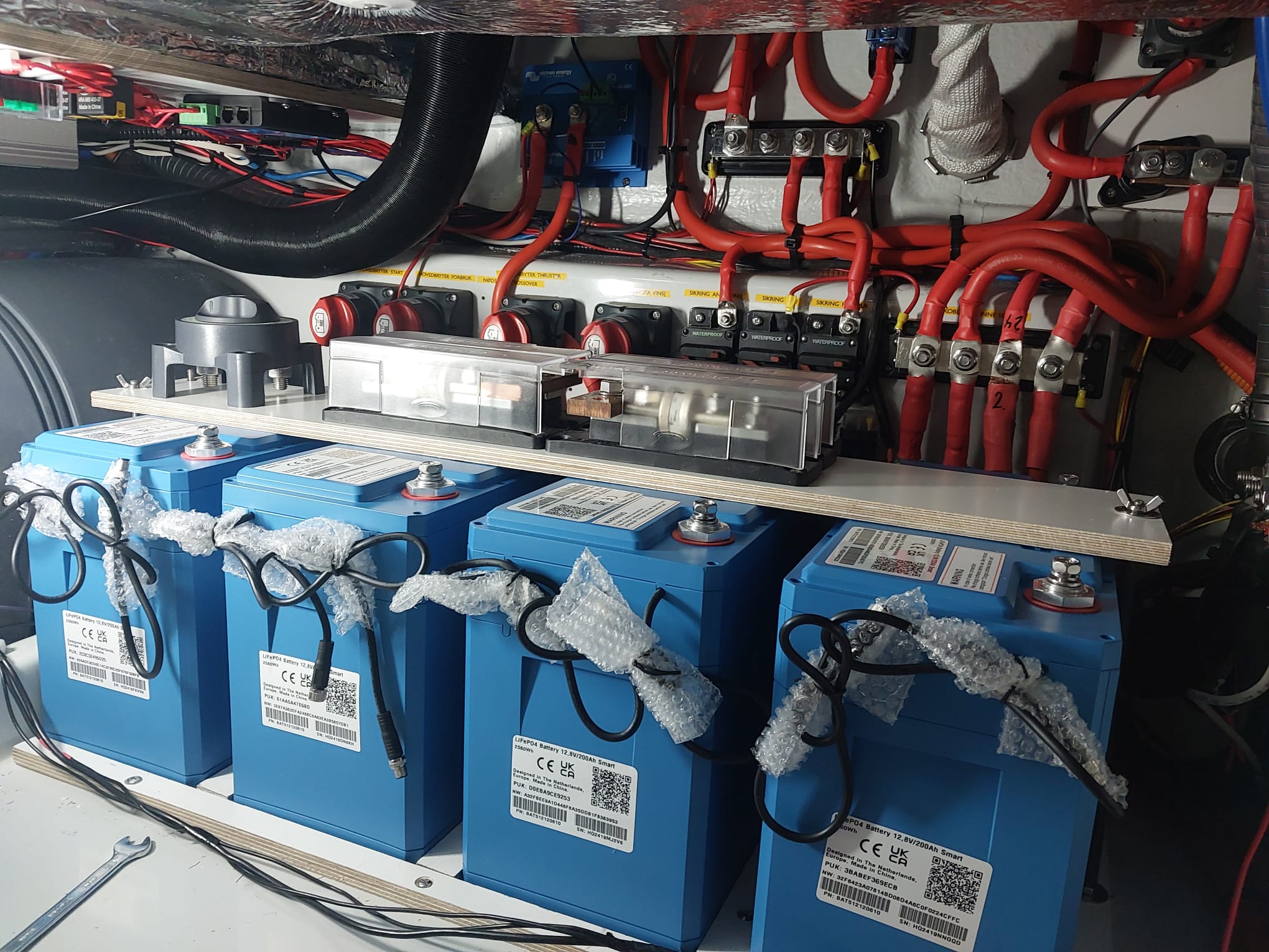
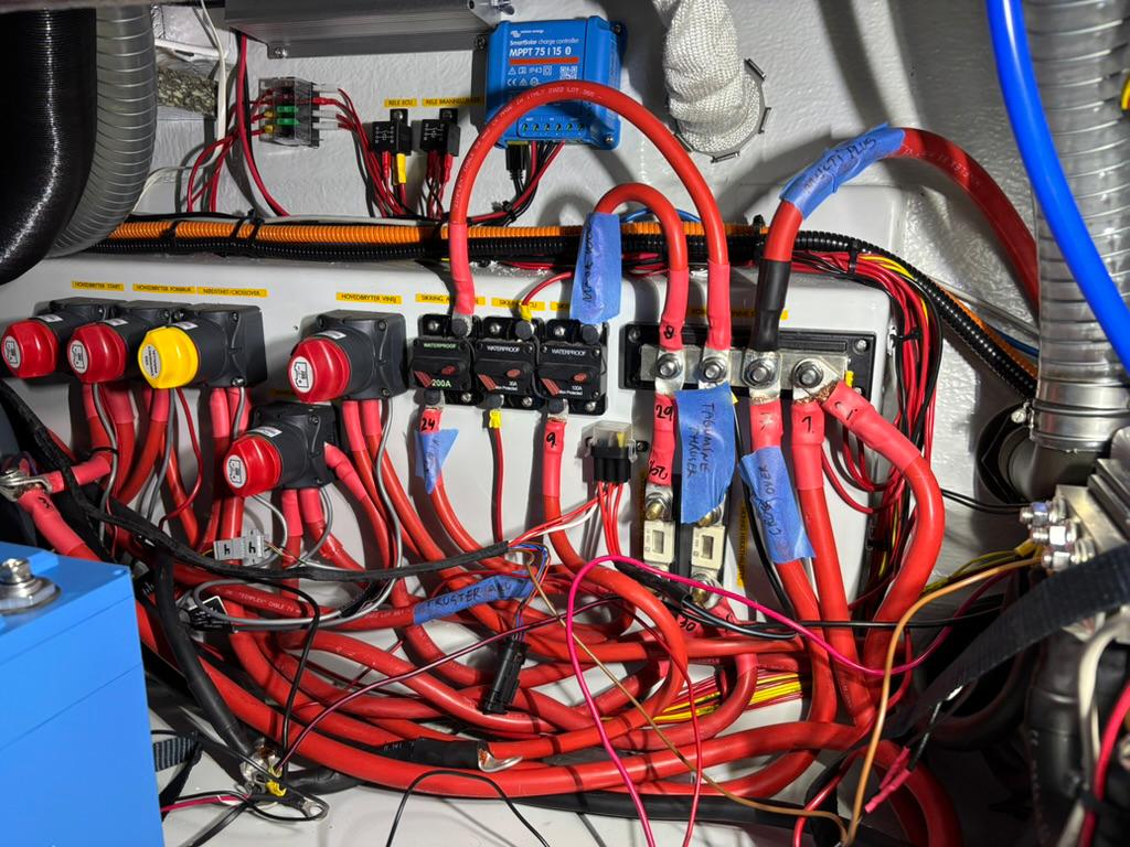
All done: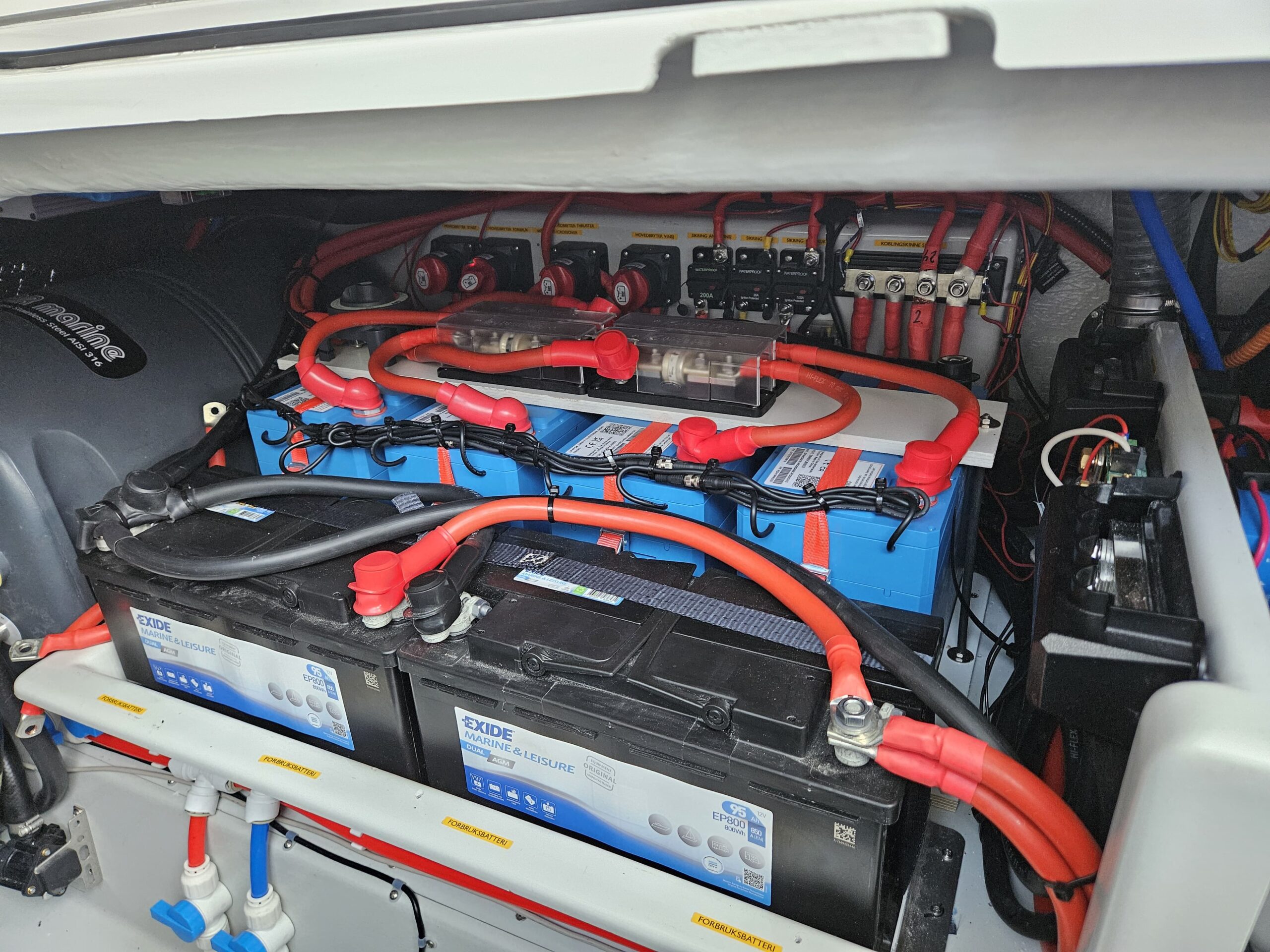
The Alternator
There is some talk in the Skilso FB group of “do nothing”, “the alternator is protected” etc.
At least in case of the 6LY440 engine this could not be further from the truth. With a half discharged Lithium bank within 5 minutes at 1000 engine RPM you are looking at a temperature of well over 120C on the windings. Maybe the alternator does not melt immediately but certainly the service life will be significantly reduced.
There is no mention anywhere in the service manual or in the manufacturer documents about the alternator having any kind of thermal protection at all either. Putting your head in the sand is a terrible idea here. While an AGM bank rapidly reduces it’s charging current, a Lithium bank can draw full current from the alternator for hours on end.
I used a Mastervolt Alpha Pro III alternator controller. It has an option to fit a temperature sensor to the case of the alternator and implement a field current limitation.
First the alternator needs to be modified and the internal regulator removed. Then the rotor needs to be completely decoupled from the case. A Chrysler part and some modification works, I let an alternator shop do it and they knew what to do.
Here is the modified alternator with the connector fitted by the repair shop and a couple wires slid on: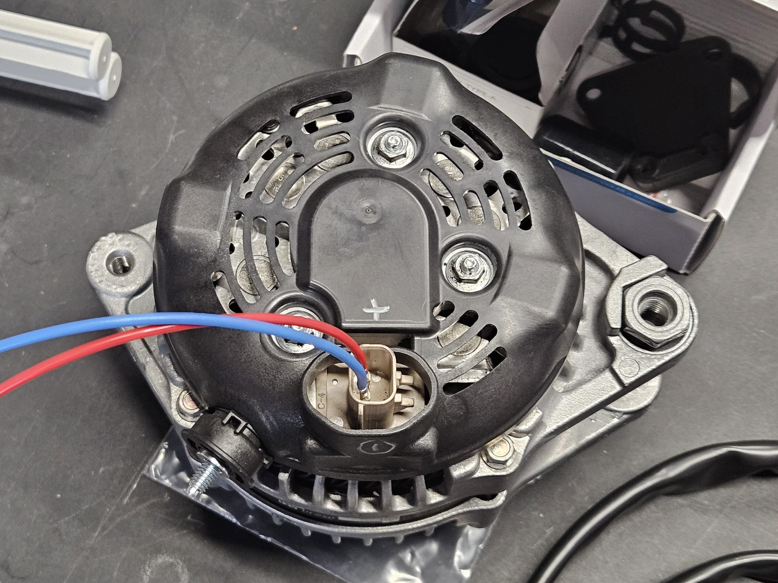
I used an automotive potting compound, because using a connector would have required cutting the plastic shield, and added a Deutsch two pin connector: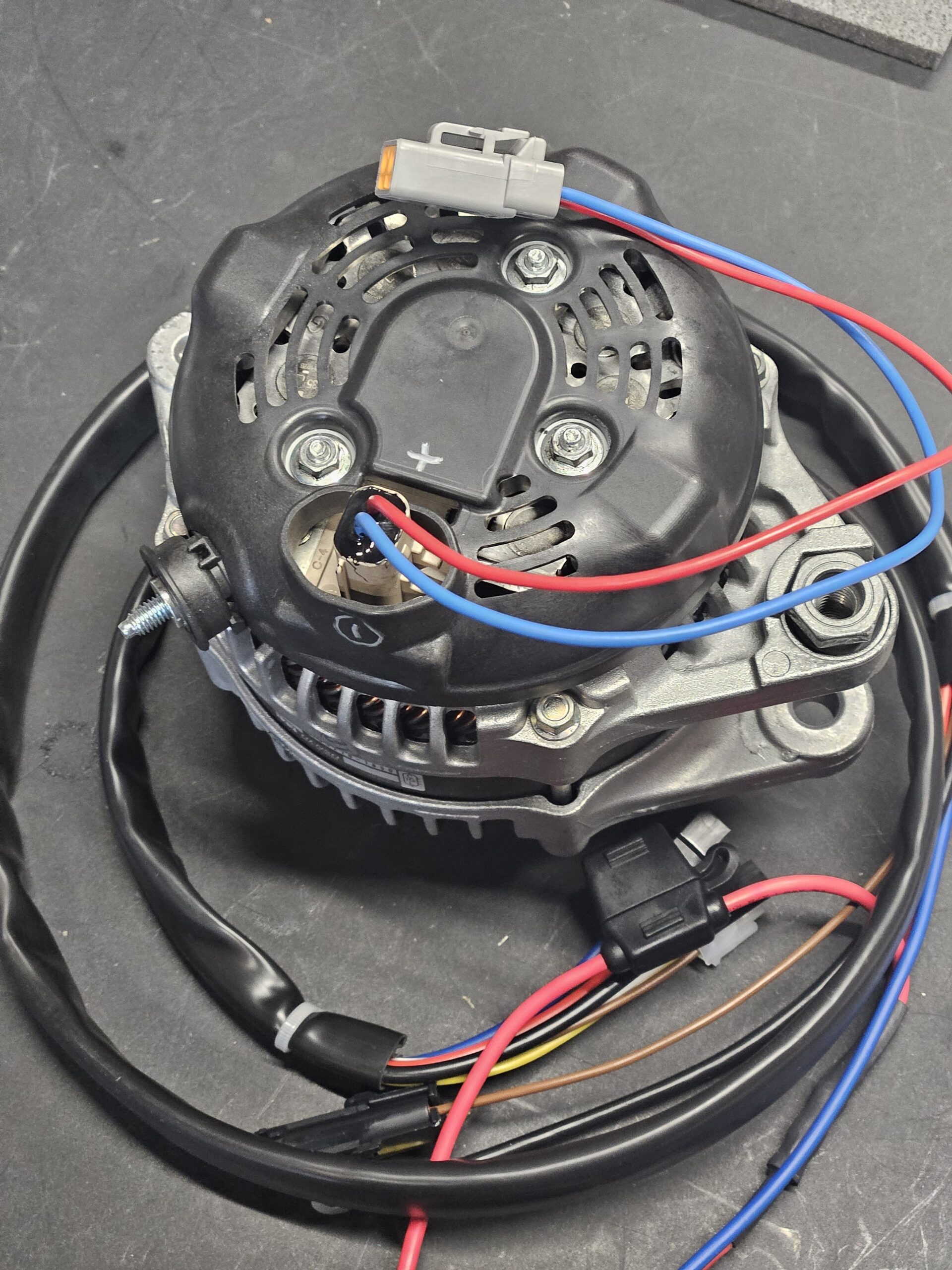
Alternator re-fitted: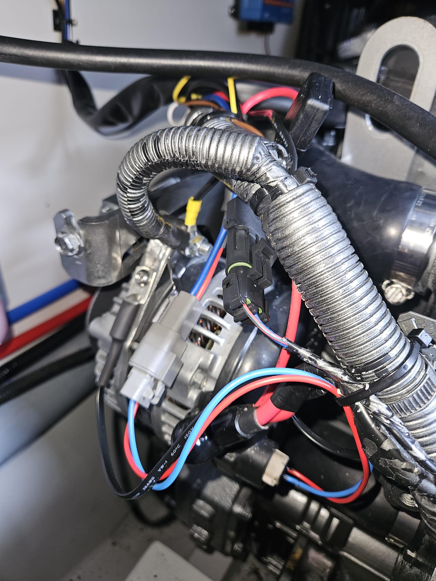
You can see the temperature probe on the case.
The Alpha Pro III I fitted on the front bulkhead: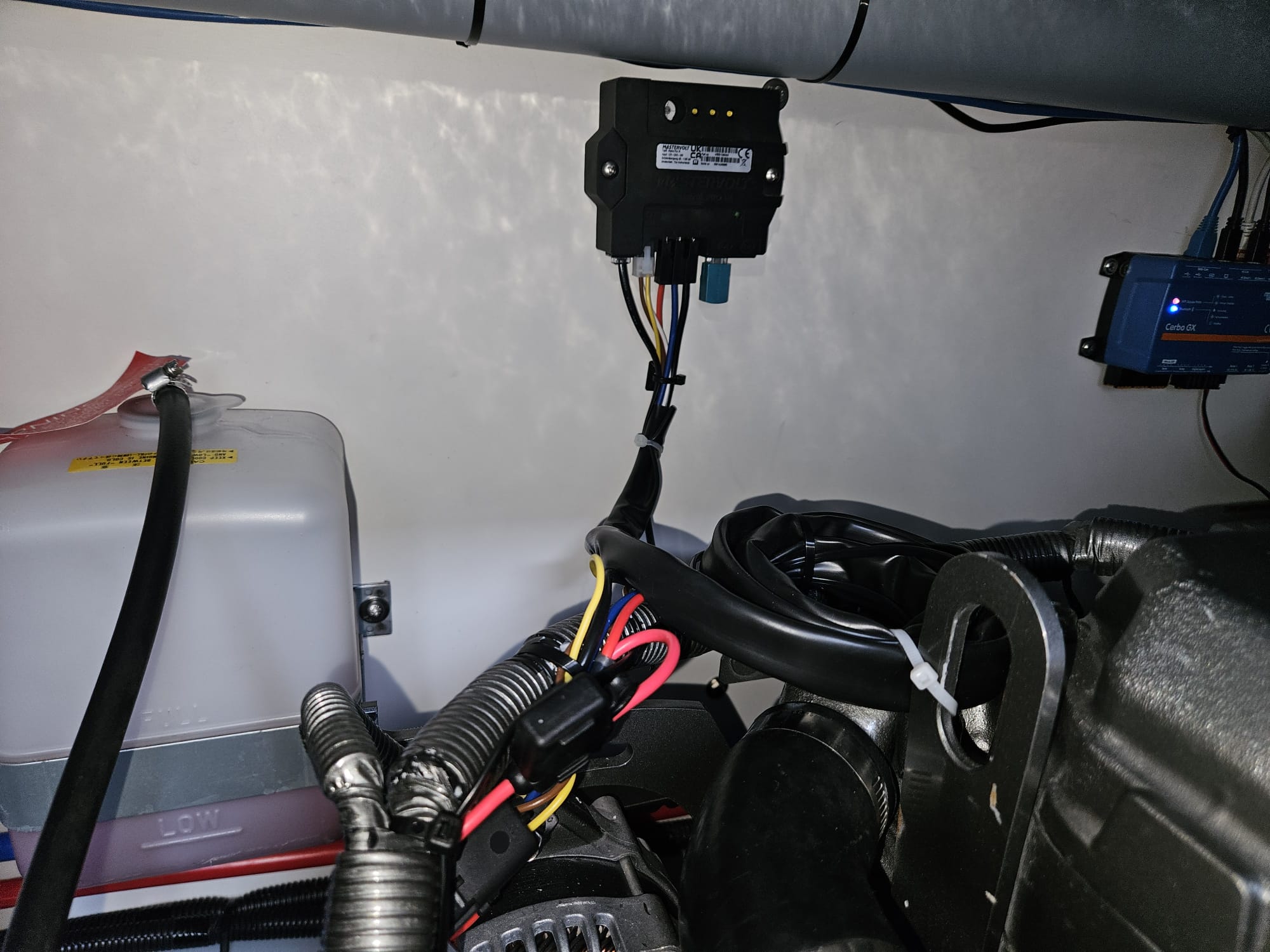
You need a MasterBus to USB interface from MasterVolt to program the Alpha Pro III. The Alpha Pro also converts the alternator to a full three stage charger – it can do the correct absorption, bulk and float charging.
I set a case temperature limit of 95C and to start reducing the field current from 75C. The result is a peak of 110C and stabilized temperature of 105C at the windings: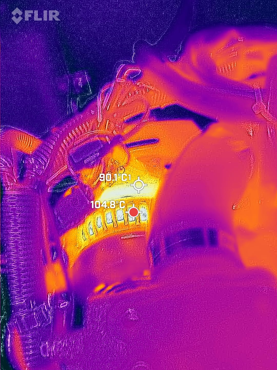
And yes, I used a thermal camera for all my tests, because “trust me bro” from Social media doesn’t cut it.
The last issue was the charging detection in the Yanmar ECU. Unfortunately the Alpha Pro III does not provide a proper LAMP output. So at the moment I just wired permanent 12V into CHG_SW on the ECU. This still gives an alarm (Charging error) if you turn the ignition on and do not start the engine for over 1 minute, but at least during engine running you get no alarms.
The correct solution is to install a small logic board that will compare the voltage at the alternator output with the sense voltage. Due to losses in cables, when the alternator is charging the output voltage is always higher than the sense voltage. And based on that it is possible to drive a relay to make the Yanmar ECU happy. A project for the winter 🙂
Conclusion
All in all, it was quite the project, but it is done correctly and should last a while without any issues.
I have been running the setup this summer, and I can easily go 96h without any shore power when having all the appliances on, using the electric kettle and having active Starlink.